Simple Chucking Socket & Spigot Marking Gauges
by Chas Jones
In Woodturning most things vary every time you pick up a piece of wood, one thing that stays consistent and does not vary over time are the jaw dimensions of your chosen chuck system. This fact means that if you make some simple marking gauges you only ever need to research and measure the distances once, leaving the use of callipers, rules etc. to the more creative tasks.
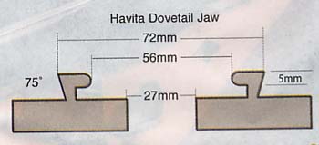
First things first, research the nominal dimensions specified for your particular jaws, these are the dimensions that give you the optimum jaw to wood contact without bruising the socket or spigot., they can usually be found in drawing form in the manufactures literature, or at the very least listed some where in the text.
If all else fails you will need to set your jaws in a position that gives a true circle and check the internal and external dimensions.
|
|
|
|
|
|
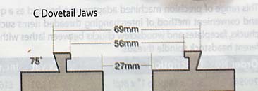
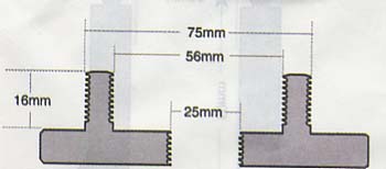
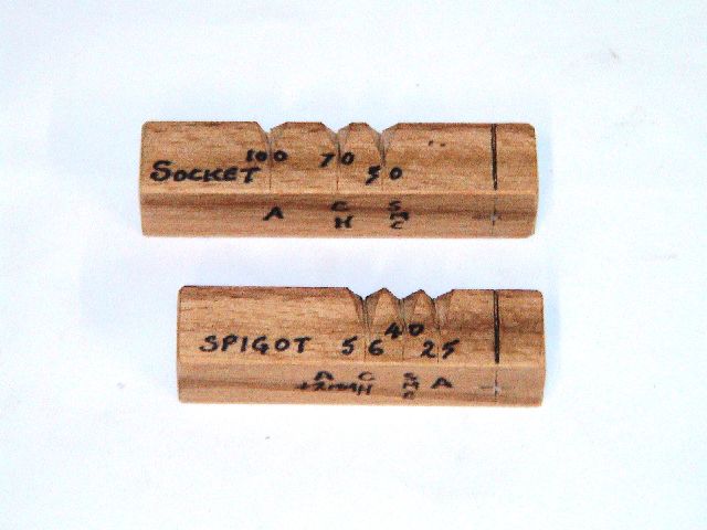
Basic construction details of my simple Socket and Spigot marking gauges
(click on any image for a larger view)
The dimensions for the pencil guides will obviously have to be adjusted to suit your particular jaws, in use it is easy to make slight adjustments to the final dimensions of the sockets and spigots based on the obtained guide marks to suit a particular task or as in my case cover the difference between an optimum 69 and 72 mm for the differing jaws shown above, I also have one little used spigot set that is just 4mm bigger than my regular 56mm, I cover this by enlarging the spigot by eye. (I have reminder note on the gage)
|
|
|
|
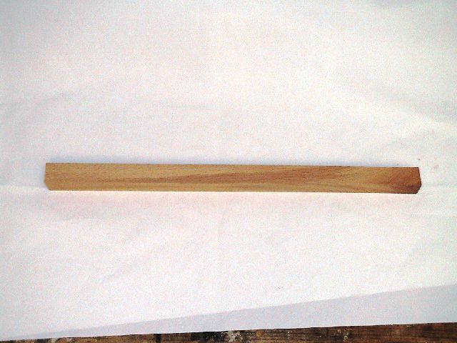
Select and prepare a suitable piece of Beech or similar wood from the scrap box, 15-20mm sq x 200mm or more long, (5/8-3/4 x 8") |
Mark out 2 sections, In this case I have marked them at 90mm and 80mm long. (3 1/2-3 1/8") (I prefer them to be differing lengths to aid visual selection from the tool draw.) |
|
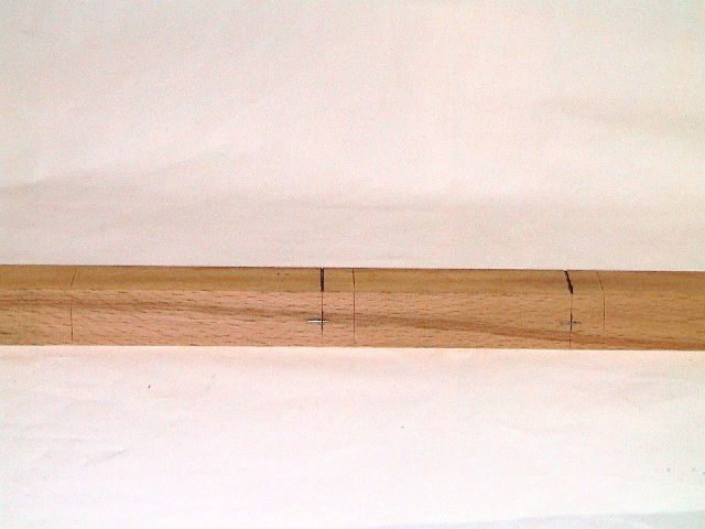
Now mark a distinct reference cut line on the top face (fill with pencil) 10mm (3/8") from the right hand end of each section, and transfer a witness line down the face and establish a centre mark on this face line.
Select 2 suitable Panel Pins or Brads and selecting a drill size slightly smaller than their diameter, drill 2 holes through the face of the piece on the centres marked, (pillar drill preferred to ensure they are square.) |
|
|
|
|
|
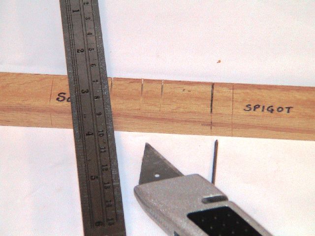
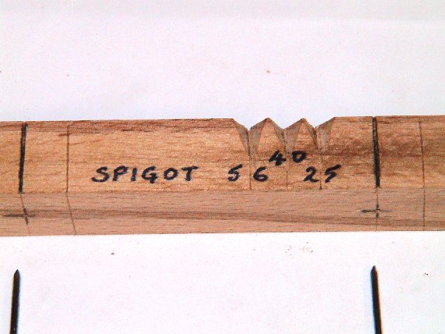
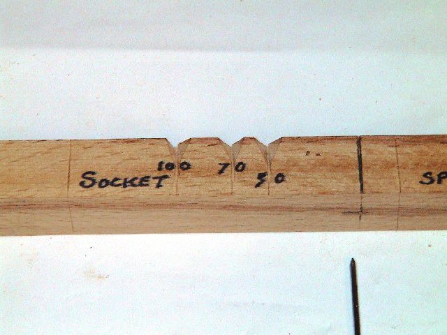
Using the reference line as the datum, mark with a marking knife the required radius dimensions along the top face to suit your jaws. This is a good time to annotate the gauge sections as Socket and Spigot to avoid confusion. Having marked and checked the dimensions make a series of cuts with a fine saw blade at an angle as shown above centred on the radius markings. |
Now with a sharp Craft knife or chisel cut a Vee at each saw cut position wide enough to take a sharpened pencil. |
|
|
|
|
Mark the Vees ' with the respective Spigot |
and Socket diameters. |
|
|
|
|
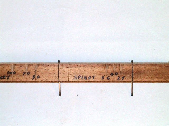
Now drive the Panel Pins through the previously drilled holes until the points protrude on the back face 2-3mm (1/16-3/32") |
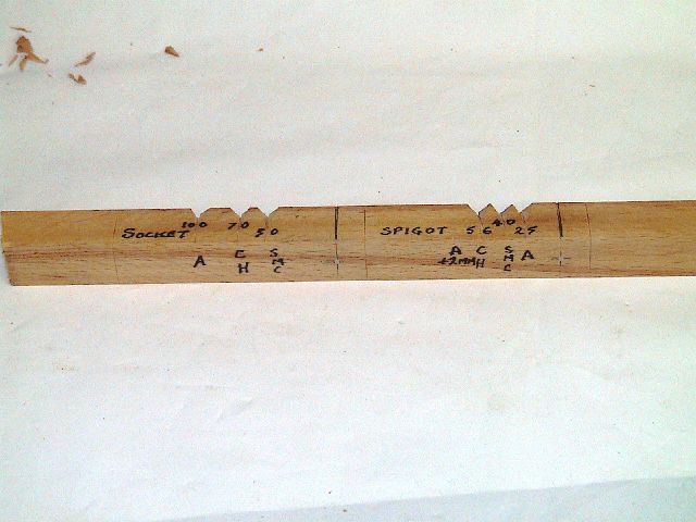
Cut off surplus pin heads and file smooth. Jaw type codes can be added to this face as reminders for those times when an intellectual aberration occurs. |
|
|
|
|
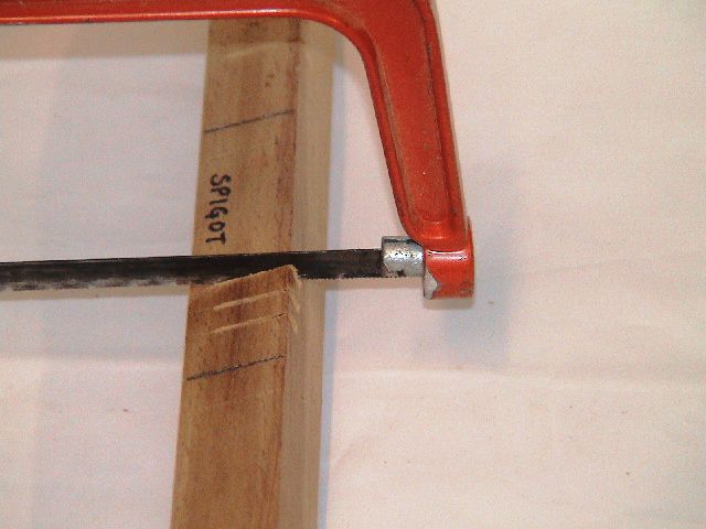
All that remains is to saw the two sections to length and round off the sharp corners for the sake of the fingers, I prefer not to sand the ends too smooth as an aid to handling. |
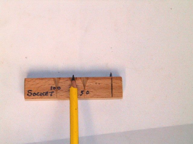
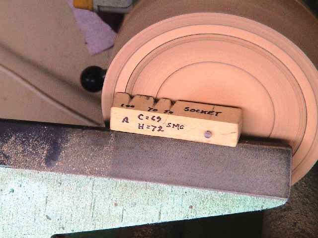
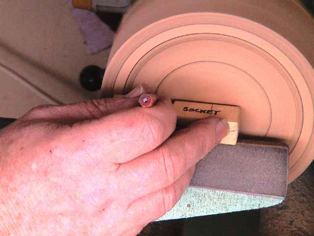
This is how the marking pencil is presented after locating the pin point in a witness centre marked with a skew chisel or similar as shown below. |
|
|
|
|
|
|
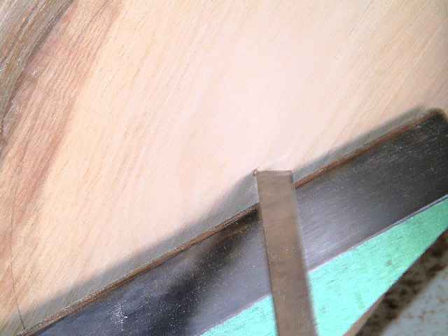
Here you can see an earlier incarnation in use. Note the lathe is spinning in both shots
|
|